
Page 248 - Aircraft Stuctures for Engineering Student
P. 248
7.4 Fabrication of structural components 229
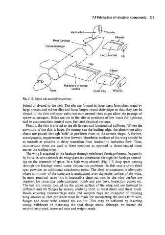
Vertical tail -!k Rudder
Rear fuselage
Centre fuselage
Mainplane or centre
section
M o s e Outer wing Wing tip
Fig. 7.10 Typical sub-assembly breakdown.
bolted or riveted to the web. The ribs are formed in three parts from sheet metal by
large presses and rubber dies and have flanges round their edges so that they can be
riveted to the skin and spar webs; cut-outs around their edges allow the passage of
spanwise stringers. Holes are cut in the ribs at positions of low stress for lightness
and to accommodate control runs, fuel and electrical systems.
Finally, the skin is riveted to the rib flanges and longitudinal stiffeners. Where the
curvature of the skin is large, for example at the leading edge, the aluminium alloy
sheets are passed through ‘rolls’ to pre-form them to the correct shape. A further,
aerodynamic, requirement is that forward chordwise sections of the wing should be
as smooth as possible to delay transition from laminar to turbulent flow. Thus,
countersunk rivets are used in these positions as opposed to dome-headed rivets
nearer the trailing edge.
The wing is attached to the fuselage through reinforced fuselage frames, frequently
by bolts. In some aircraft the wing spars are continuous through the fuselage depend-
ing on the demands of space. In a high wing aircraft (Fig. 7.7) deep spars passing
througn the fuselage would cause obstruction problems. In this case a short third
spar provides an additional attachment point. The ideal arrangement is obviously
where continuity of the structure is maintained over the entire surface of the wing.
In most practical cases this is impossible since cut-outs in the wing surface are
required for retracting undercarriages, bomb and gun bays, inspection panels etc.
The last are usually located on the under surface of the wing and are fastened to
stiffeners and rib flanges by screws, enabling them to resist direct and shear loads.
Doors covering undercarriage wells and weapon bays are incapable of resisting
wing stresses so that provision must be made for transferring the loads from skin,
flanges and shear webs around the cut-out. This may be achieved by inserting
strong bulkheads or increasing the spar flange areas, although, no matter the
method employed, increased cost and weight result.