
Page 253 - Aircraft Stuctures for Engineering Student
P. 253
234 Airworthiness and airframe loads
nl (limit load)
- Flight
speed
I Negative stall
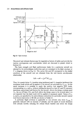
Fig. 8.1 Flight envelope.
The proof and ultimate factors may be regarded as factors of safety and provide for
various contingencies and uncertainties which are discussed in greater detail in
Section 8.2.
The basic strength and fight performance limits for a particular aircraft are
selected by the airworthiness authorities and are contained in theflight envelope or
Y-n diagram shown in Fig. 8.1. The curves OA and OF correspond to the stalled
condition of the aircraft and are obtained from the well known aerodynamic
relationship
Lift = n w = f p v~sc~:~~
Thus, for speeds below VA (positive wing incidence) and VF (negative incidence) the
maximum loads which can be applied to the aircraft are governed by CL,max. As the
speed increases it is possible to apply the positive and negative limit loads,
corresponding to nl and n3, without stalling the aircraft so that AC and FE represent
maximum operational load factors for the aircraft. Above the design cruising speed
V,, the cut-off lines CDI and D2E relieve the design cases to be covered since it is
not expected that the limit loads will be applied at maximum speed. Values of nl,
n2 and n3 are specified by the airworthiness authorities for particular aircraft; typical
load factors laid down in BCAR are shown in Table 8.1.
A particular flight envelope is applicable to one altitude only since CL,max is
generally reduced with an increase of altitude, and the speed of sound decreases
with altitude thereby reducing the critical Mach number and hence the design