
Page 258 - Aircraft Stuctures for Engineering Student
P. 258
8.3 Aircraft inertia loads 239
LkkJ
0 CG (F, 8)
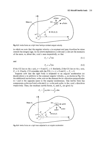
Fig. 8.3 Inertia forces on a rigid mass having a constant angular velocity.
in which we note that the angular velocity u is constant and may therefore be taken
outside the integral sign. In the above expressions J x drn and J y dm are the moments
of the mass, nz, about the y and x axes respectively, so that
Fy = w2m (8.1)
and
F,, = JJin (8.2)
If the CG lies on the x axis, J = 0 and F,, = 0. Similarly, if the CG lies on the y axis,
Fy = 0. Clearly, if 0 coincides with the CG, X = J = 0 and F, = F,. = 0.
Suppose now that the rigid body is subjected to an angular acceleration (or
deceleration) Q! in addition to the constant angular velocity, w, as shown in Fig. 8.4.
An additional inertia force, curSrn, acts on the element Srn in a direction perpendicular
to r and in the opposite sense to the angular acceleration. This inertia force has
components ar6m cos e and tur6nt sin 8, i.e. axbin and aySi71, in the y and x directions
respectively. Thus, the resultant inertia forces, Fy and F', are given by
J S
Fy= aydrn=cr ydm
Fig. 8.4 Inertia forces on a rigid mass subjected to an angular acceleration.