
Page 263 - Aircraft Stuctures for Engineering Student
P. 263
244 Airworthiness and airframe loads
We shall now consider the calculation of aircraft loads corresponding to the flight
conditions specified by flight envelopes. There are, in fact, an infinite number of
flight conditions within the boundary of the flight envelope although, structurally,
those represented by the boundary are the most severe. Furthermore, it is usually
found that the corners A, C, D1, DZ, E and F (see Fig. 8.1) are more critical than
points on the boundary between the corners so that, in practice, only the six
conditions corresponding to these corner points need be investigated for each flight
envelope.
In symmetric manoeuvres we consider the motion of the aircraft initiated by move-
ment of the control surfaces in the plane of symmetry. Examples of such manoeuvres
are loops, straight pull-outs and bunts, and the calculations involve the determination
of lift, drag and tailplane loads at given flight speeds and altitudes. The effects of
atmospheric turbulence and gusts are discussed in Section 8.6.
8.4.1 Level flight
Although steady level flight is not a manoeuvre in the strict sense of the word, it is a
useful condition to investigate initially since it establishes points of load application
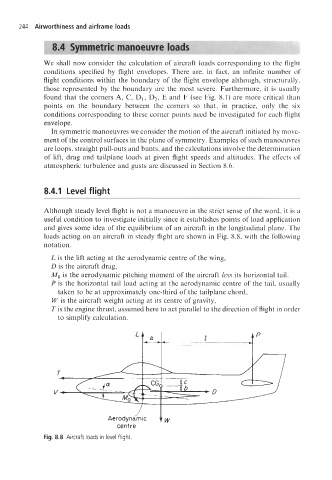
and gives some idea of the equilibrium of an aircraft in the longitudinal plane. The
loads acting on an aircraft in steady flight are shown in Fig. 8.8, with the following
notation.
L is the lift acting at the aerodynamic centre of the wing,
D is the aircraft drag,
Mo is the aerodynamic pitching moment of the aircraft less its horizontal tail,
P is the horizontal tail load acting at the aerodynamic centre of the tail, usually
taken to be at approximately one-third of the tailplane chord,
W is the aircraft weight acting at its centre of gravity,
T is the engine thrust, assumed here to act parallel to the direction of flight in order
to simplify calculation.
LA ~ I
centre
Fig. 8.8 Aircraft loads in level flight.