
Page 265 - Aircraft Stuctures for Engineering Student
P. 265
246 Airworthiness and airframe loads
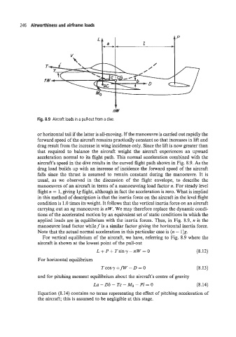
Fig. 8.9 Aircraft loads in a pull-out from a dive.
or horizontal tail if the latter is all-moving. If the manoeuvre is carried out rapidly the
forward speed of the aircraft remains practically constant so that increases in lift and
drag result from the increase in wing incidence only. Since the lift is now greater than
that required to balance the aircraft weight the aircraft experiences an upward
acceleration normal to its flight path. This normal acceleration combined with the
aircraft's speed in the dive results in the curved flight path shown in Fig. 8.9. As the
drag load builds up with an increase of incidence the forward speed of the aircraft
falls since the thrust is assumed to remain constant during the manoeuvre. It is
usual, as we observed in the discussion of the flight envelope, to describe the
manoeuvres of an aircraft in terms of a manoeuvring load factor n. For steady level
flight n = 1, giving lg flight, although in fact the acceleration is zero. What is implied
in this method of description is that the inertia force on the aircraft in the level flight
condition is 1 .O times its weight. It follows that the vertical inertia force on an aircraft
carrying out an ng manoeuvre is n W. We may therefore replace the dynamic condi-
tions of the accelerated motion by an equivalent set of static conditions in which the
applied loads are in equilibrium with the inertia forces. Thus, in Fig. 8.9, n is the
manoeuvre load factor whilef is a similar factor giving the horizontal inertia force.
Note that the actual normal acceleration in this particular case is (n - 1)g.
For vertical equilibrium of the aircraft, we have, referring to Fig. 8.9 where the
aircraft is shown at the lowest point of the pull-out
L + P+ Tsiny - nW = 0 (8.12)
For horizontal equilibrium
T COSY +fw - D = 0 (8.13)
and for pitching moment equilibrium about the aircraft's centre of gravity
La - Db - Tc - Mo - PI = 0 (8.14)
Equation (8.14) contains no terms representing the effect of pitching acceleration of
the aircraft; this is assumed to be negligible at this stage.