
Page 296 - Aircraft Stuctures for Engineering Student
P. 296
9.1 Bending of open and closed section beams 277
and displacements, investigate the effect of choice of section on the positive directions
of these parameters and discuss the determination of the components of a bending
moment applied in any longitudinal plane.
9.1 .I Sign conventions and notation
"- e--- I-IY.II*IIII-"-PICI.-
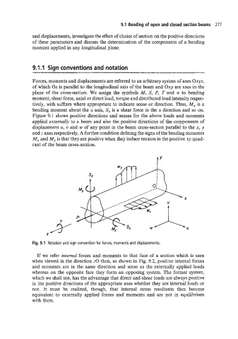
Forces, moments and displacements are referred to an arbitrary system of axes Oxy~,
of which Oz is parallel to the longitudinal axis of the beam and Oxy are axes in the
plane of the cross-section. We assign the symbols M, S, P, T and w to bending
moment, shear force, axial or direct load, torque and distributed load intensity respec-
tively, with suffixes where appropriate to indicate sense or direction. Thus, M, is a
bending moment about the x axis, S, is a shear force in the x direction and so on.
Figure 9.1 shows positive directions and senses for the above loads and moments
applied externally to a beam and also the positive directions of the components of
displacement u, w and w of any point in the beam cross-section parallel to the x, y
and z axes respectively. A further condition defining the signs of the bending moments
M, and My is that they are positive when they induce tension in the positive xy quad-
rant of the beam cross-section.
Fig. 9.1 Notation and sign convention for forces, moments and displacements.
If we refer internal forces and moments to that face of a section which is seen
when viewed in the direction z0 then, as shown in Fig. 9.2, positive internal forces
and moments are in the same direction and sense as the externally applied loads
whereas on the opposite face they form an opposing system. The former system,
which we shall use, has the advantage that direct and shear loads are always positive
in the positive directions of the appropriate axes whether they are internal loads or
not. It must be realized, though, that internal stress resultants then become
equivalent to externally applied forces and moments and are not in equilibrium
with them.