
Page 291 - Aircraft Stuctures for Engineering Student
P. 291
272 Airworthiness and airframe loads
11 Rice, J. R., Mechanics of crack tip deformation and extension by fatigue. In: Fatigue
Crack Propagation, American Society for Testing Materials, Philadelphia, USA, ASTM
STP 415, June, 1967.
12 Paris, P. C., The fracture mechanics approach to fatigue. In: Fatigue - An Znterdisciplinaty
Approach, Syracuse University Press, New York, USA, 1964.
13 Forman, R. G., Numerical analysis of crack propagation in cyclic-loaded structures,
Trans. Am. Soc. Mech. Engrs, 89, Series D, No. 3, Sept. 1967.
Freudenthal, A. M., Fatigue in Aircraft Structures, Academic Press, New York, 1956.
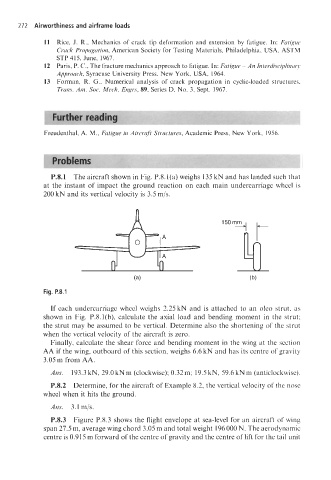
P.8.1 The aircraft shown in Fig. P.8.l(a) weighs 135 kN and has landed such that
at the instant of impact the ground reaction on each main undercarriage wheel is
200 kN and its vertical velocity is 3.5 mjs.
Fig. P.8.1
If each undercarriage wheel weighs 2.25 kN and is attached to an oleo strut, as
shown in Fig. P.8.l(b), calculate the axial load and bending moment in the strut;
the strut may be assumed to be vertical. Determine also the shortening of the strut
when the vertical velocity of the aircraft is zero.
Finally, calculate the shear force and bending moment in the wing at the section
AA if the wing, outboard of this section, weighs 6.6 kN and has its centre of gravity
3.05 m from AA.
Ans. 193.3 kN, 29.0 kNm (clockwise); 0.32m; 19.5 kN, 59.6 kN m (anticlockwise).
P.8.2 Determine, for the aircraft of Example 8.2, the vertical velocity of the nose
wheel when it hits the ground.
Ans. 3.1 mjs.
P.8.3 Figure P.8.3 shows the flight envelope at sea-level for an aircraft of wing
span 27.5 m, average wing chord 3.05 m and total weight 196 000 N. The aerodynamic
centre is 0.91 5 m forward of the centre of gravity and the centre of lift for the tail unit