
Page 288 - Aircraft Stuctures for Engineering Student
P. 288
8.7 Fatigue 269
s
S
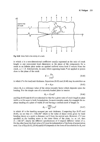
Fig. 8.20 Stress field in the vicinity of a crack.
in which a is a non-dimensional coefficient usually expressed as the ratio of crack
length to any convenient local dimension in the plane of the component; for a
crack in an infinite plate under an applied uniform stress level S remote from the
crack, a = 1 .O. Alternatively, in cases where opposing loads P are applied at points
close to the plane of the crack
(8.64)
in which Pis the load/unit thickness. Equations (8.63) and (8.64) may be rewritten as
K = Koa (8.65)
where &, is a reference value of the stress intensity factor which depends upon the
loading. For the simple case of a remotely loaded plate in tension
KO = S(~a)i (8.66)
and Eqs (8.65) and (8.63) are identical so that for a given ratio of crack length to plate
width a is the same in both formulations. In more complex cases, for example the in-
plane bending of a plate of width 2b and having a central crack of length 2u
3Ma
KO = 3 (8.67)
I
(TU)?
in which M is the bending moment per unit thickness. Comparing Eqs (8.67) and
(8.63), we see that S = 3Ma/4b3 which is the value of direct stress given by 5asic
bending theory at a point a distance fa/2 from the central axis. However, if S was
specified as the bending stress in the outer fibres of the plate, i.e. at &b, then
S = 3M/2b2; clearly the different specifications of S require different values of a.
On the other hand the final value of K must be independent of the form of presentation
used. Use of Eqs (8.63), (8.64) and (8.65) depends on the form of the solution for KO and