
Page 287 - Aircraft Stuctures for Engineering Student
P. 287
268 Airworthiness and airframe loads
@ @ front
Crack
Crack
front
front
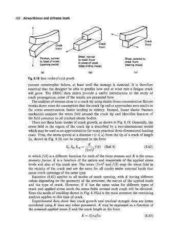
1 Tension, normal Shear, normal Shear, parallel to
to crack front
to faces of crack
crack front
in plane of crack
(opening mode)
(tearing mode)
(edge sliding mode)
(a) ( b) (C)
Fig. 8.19 Basic modes of crack growth.
prevent catastrophic failure, at least until the damage is detected. It is therefore
essential that the designer be able to predict how and at what rate a fatigue crack
will grow. The ESDU data sheets provide a useful introduction to the study of
crack propagation; some of the results are presented here.
The analysis of stresses close to a crack tip using elastic stress concentration factors
breaks down since the assumption that the crack tip radius approaches zero results in
the stress concentration factor tending to infinity. Instead, linear elastic fracture
mechanics analyses the stress field around the crack tip and identifies features of
the field common to all cracked elastic bodies.
There are three basic modes of crack growth, as shown in Fig. 8.19. Generally, the
stress field in the region of the crack tip is described by a two-dimensional model
which may be used as an approximation for many practical three-dimensional loading
cases. Thus, the stress system at a distance I (I < u) from the tip of a crack of length
24 shown in Fig. 8.20, can be expressed in the form
(8.62)
in whichf(8) is a different function for each of the three stresses and K is the stress
intensity factor; K is a function of the nature and magnitude of the applied stress
levels and also of the crack size. The terms (2xr)f andf(8) map the stress field in
the vicinity of the crack and are the same for all cracks under external loads that
cause crack openings of the same type.
Equation (8.62) applies to all modes of crack opening, with K having different
values depending on the geometry of the structure, the nature of the applied loads
and the type of crack. However, if K has the same value for different types of
crack and applied stress levels the stress fields around each crack will be identical.
Since the mode of cracking shown in Fig. 8.19(a) is the most common the remaining
analysis applies to this type of crack.
Experimental data show that crack growth and residual strength data are better
correlated using K than any other parameter. K may be expressed as a function of
the nominal applied stress S and the crack length in the form
K = S(.rru)fa (8.63)