
Page 326 - Aircraft Stuctures for Engineering Student
P. 326
9.5 Torsion of closed section beams 307
Taking moments about the point 2 we have
or
Spa sin e 1 loa (- ?s: + 58.7~~) dsl
SY(& + 9a) =
1152a3 0
We may replace sin 6’ by sin(O1 - 0,) = sin el cos O2 - cos O1 sin Q2 where sin O1 =
15/17, cosO2 = 8/10, cosQ1 = 8/17 and sine2 = 6/10. Substituting these values
and integrating Eq. (v) gives
& = -3.35a
which means that the shear centre is inside the beam section.
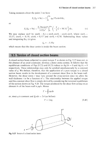
A closed section beam subjected to a pure torque T as shown in Fig. 9.27 does not, in
the absence of an axial constraint, develop a direct stress system. It follows that the
equilibrium conditions of Eqs (9.22) and (9.23) reduce to dq/ds = 0 and dq/dz = 0
respectively. These relationships may only be satisfied simultaneously by a constant
value of q. We deduce, therefore, that the application of a pure torque to a closed
section beam results in the development of a constant shear flow in the beam wall.
However, the shear stress 7 may vary around the cross-section since we allow the
wall thickness t to be a function of s. The relationship between the applied torque
and this constant shear flow is simply derived by considering the torsional equilibrium
of the section shown in Fig. 9.28. The torque produced by the shear flow acting on an
element 6s of the beam wall is pq6s. Hence
or, since q is constant and fpds = 2A (as before)
T = 2Aq (9.49)
X
z
Fig. 9.27 Torsion of a closed section beam