
Page 329 - Aircraft Stuctures for Engineering Student
P. 329
3 10 Open and closed, thin-walled beams
constant shear flow. Thus
Replacing q from Eq. (9.49) we have
(9.53)
where
The sign of the warping displacement in Eq. (9.53) is governed by the sign of the
applied torque T and the signs of the parameters So, and Aos. Having specified
initially that a positive torque is anticlockwise, the signs of So, and Aos are fixed in
that So, is positive when s is positive, i.e. s is taken as positive in an anticlockwise
sense, and Aos is positive when, as before, p (see Fig. 9.29) is positive.
We have noted that the longitudinal strain E, is zero in a closed section beam sub-
jected to a pure torque. This means that all sections of the beam must possess identical
warping distributions. In other words longitudinal generators of the beam surface
remain unchanged in length although subjected to axial displacement.
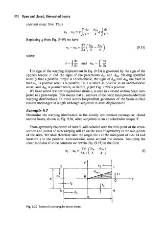
Example 9.7
Determine the warping distribution in the doubly symmetrical rectangular, closed
section beam, shown in Fig. 9.30, when subjected to an anticlockwise torque T.
From symmetry the centre of twist R will coincide with the mid-point of the cross-
section and points of zero warping will lie on the axes of symmetry at the mid-points
of the sides. We shall therefore take the origin for s at the mid-point of side 14 and
measure s in the positive, anticlockwise, sense around the section. Assuming the
shear modulus G to be constant we rewrite Eq. (9.53) in the form
2
I t
3t--54 l4
a
t
Fig. 9.30 Torsion of a rectangular section beam.