
Page 339 - Aircraft Stuctures for Engineering Student
P. 339
320 Open and closed, thin-walled beams
The warping distribution is obtained using Eq. (9.68) in which the origin for s (and
hence AR) is taken at the intersection of the web and the axis of symmetry where the
warping is zero. Further, the centre of twist R of the section coincides with its shear
centre S whose position is found using the method described in Section 9.3; this gives
Cs = 8.04mm. In the wall 02
AR = 4 x 8.04~1 (pR is positive)
so that
io io3
~02 -2 x 4 x 8.04~1 x = -0.Ols1
=
25000 x 316.7
i.e. the warping distribution is linear in 02 and
~2 = -0.01 x 25 = -0.25mm
In the wall 21
AR = 4 x 8.04 x 25 -4 x 25s2
in which the area swept out by the generator in the wall 21 provides a negative con-
tribution to the total swept area AR. Thus
io io3
=
~21 -25(8.04 - ~2)
25 000 x 3 16.7
or
=
~21 -0.03(8.04 - ~2) (ii)
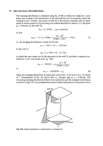
Again the warping distribution is linear and varies from -0.25 mm at 2 to f0.54 mm
at 1. Examination of Eq. (ii) shows that w~~ changes sign at s., = 8.04mm. The
remaining warping distribution follows from symmetry and the complete distribution
is shown in Fig. 9.39. In unsymmetrical section beams the position of the point of zero
4
Fig. 9.39 Warping distribution in channel section of Example 9.8.