
Page 341 - Aircraft Stuctures for Engineering Student
P. 341
322 Open and closed, thin-walled beams
Finally
A34 = 1 1 1.5 + 4 x 25s3 (iii)
Substituting for AI2, A23 and A34 from Eqs (i), (ii) and (iii) in Eq. (9.69) we have
2Ak = [ 61 25 x 1.15~1 dsl + 2(312.5 - 4.02s2)2.5ds2
200
1
+ jy 2( 1 1 1.5 + 12.54 1.5 ds3
Evaluation of Eq. (iv) gives
2Ak = 424mm2
We now examine each wall of the section in turn to determine points of zero warping.
Suppose that in the wall 12 a point of zero warping occurs at a value of s1 equal to s~,~.
Then
2 x 4 x 25sl,o = 424
from which
q0 = 16.96mm
so that a point of zero warping occurs in the wall 12 at a distance of 8.04mm from the
point 2 as before. In the web 23 let the point of zero warping occur at s2 = s~,~. Then
2 x 4 x 25 x 25 - 2 x 4 x 8.04~2.0 = 424
~
which gives ~ 2 = ,25mm (i.e. on the axis of symmetry). Clearly, from symmetry, a
further point of zero warping occurs in the flange 34 at a distance of 8.04mm from
the point 3. The warping distribution is then obtained directly using Eq. (9.68) in
which
AR = AR,O - Ak
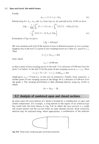
In some cases the cross-section of a beam is formed by a combination of open and
closed components. For example, a wing section in the region of an undercarriage
bay could take the form shown in Fig. 9.41 in which the nose portion is a single
cell closed section and the cut-out forms an open channel section. Such composite
sections may be analysed using, where appropriate, a combination of the methods
Fig. 9.41 Wing section comprising open and closed components