
Page 342 - Aircraft Stuctures for Engineering Student
P. 342
9.7 Analysis of combined open and closed sections 323
previously described in this chapter. We shall examine the different loading conditions
in turn.
9.7.1 Bending
It is immaterial what form the cross-section of a beam takes; the direct stresses due to
bending are given by either of Eqs (9.6) or (9.7).
9.7.2 Shear
The methods described in Sections 9.3 and 9.4 are used to determine the shear stress
distribution although, unlike the completely closed section case, shear loads must be
applied through the shear centre of the combined section, otherwise shear stresses of
the type described in Section 9.6 due to torsion will arise. Where shear loads do not
act through the shear centre its position must be found and the loading system
replaced by shear loads acting through the shear centre together with a torque; the
two loading cases are then analysed separately. Again we assume that the cross-
section of the beam remains undistorted by the loading.
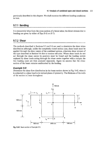
Example 9.9
Determine the shear flow distribution in the beam section shown in Fig. 9.42, when it
is subjected to a shear load in its vertical plane of symmetry. The thickness of the walls
of the section is 2 mm throughout.
i -
I
Y
t -
s4
C X
1 8
s5 -
4 9 5
_-
200 mm I 1OOmm
Fig. 9.42 Beam section of Example 9.9.