
Page 347 - Aircraft Stuctures for Engineering Student
P. 347
328 Open and closed, thin-walled beams
Fig. 9.45 Typical wing section.
governed by the particular situation surrounding the problem. For a preliminary
investigation, speed and simplicity are often of greater importance than extreme
accuracy; on the other hand a final solution must be as exact as circumstances allow.
Complex structural sections may be idealized into simpler 'mechanical model' forms
which behave, under given loading conditions, in the same, or very nearly the same,
way as the actual structure. We shall see, however, that different models of the same
structure are required to simulate actual behaviour under ditferent systems of loading.
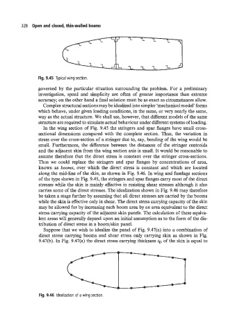
In the wing section of Fig. 9.45 the stringers and spar flanges have small cross-
sectional dimensions compared with the complete section. Thus, the variation in
stress over the cross-section of a stringer due to, say, bending of the wing would be
small. Furthermore, the difference between the distances of the stringer centroids
and the adjacent skin from the wing section axis is small. It would be reasonable to
assume therefore that the direct stress is constant over the stringer cross-sections.
Thus we could replace the stringers and spar flanges by concentrations of area,
known as booms, over which the direct stress is constant and which are located
along the mid-line of the skin, as shown in Fig. 9.46. In wing and fuselage sections
of the type shown in Fig. 9.45, the stringers and spar flanges carry most of the direct
stresses while the skin is mainly effective in resisting shear stresses although it also
carries some of the direct stresses. The idealization shown in Fig. 9.46 may therefore
be taken a stage further by assuming that all direct stresses are carried by the booms
while the skin is effective only in shear. The direct stress carrying capacity of the skin
may be allowed for by increasing each boom area by an area equivalent to the direct
stress carrying capacity of the adjacent skin panels. The calculation of these equiva-
lent areas will generally depend upon an initial assumption as to the form of the dis-
tribution of direct stress in a boom/skin panel.
Suppose that we wish to idealize the panel of Fig. 9.47(a) into a combination of
direct stress carrying booms and shear stress only carrying skin as shown in Fig.
9.47(b). In Fig. 9.47(a) the direct stress carrying thickness tD of the skin is equal to
Fig. 9.46 Idealization of a wing section.