
Page 348 - Aircraft Stuctures for Engineering Student
P. 348
9.8 Structural idealization 329
(a) Actual (b) Idealized
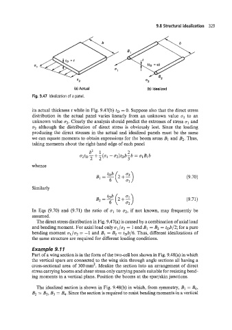
Fig. 9.47 Idealization of a panel.
its actual thickness t while in Fig. 9.47(b) tD = 0. Suppose also that the direct stress
distribution in the actual panel vanes linearly from an unknown value aI to an
unknown value a2. Clearly the analysis should predict the extremes of stress g1 and
a2 although the distribution of direct stress is obviously lost. Since the loading
producing the direct stresses in the actual and idealized panels must be the same
we can equate moments to obtain expressions for the boom areas B1 and B2. Thus,
taking moments about the right-hand edge of each panel
whence
(9.70)
Similarly
B2=y(2+2) (9.71)
In Eqs (9.70) and (9.71) the ratio of a1 to a2, if not known, may frequently be
assumed.
The direct stress distribution in Fig. 9.47(a) is caused by a combination of axial load
and bending moment. For axial load only 01 /a2 = 1 and B1 = B2 = tDb/2; for a pure
bending moment a1/g2 = -1 and B1 = B2 = tDb/6. Thus, different idealizations of
the same structure are required for different loading conditions.
Example 9.11
Part of a wing section is in the form of the two-cell box shown in Fig. 9.48(a) in which
the vertical spars are connected to the wing skin through angle sections all having a
cross-sectional area of 300mm’. Idealize the section into an arrangement of direct
stress carrying booms and shear stress only carrying panels suitable for resisting bend-
ing moments in a vertical plane. Position the booms at the spar/skin junctions.
The idealized section is shown in Fig. 9.48(b) in which, from symmetry, B1 = Bg,
B2 = Bj, B3 = B4. Since the section is required to resist bending moments in a vertical