
Page 353 - Aircraft Stuctures for Engineering Student
P. 353
334 Open and closed, thin-walled beams
area Br are q1 and q2. Then, from Fig. 9.50(b)
which simplifies to
(9.73)
Substituting for cz in Eq. (9.73) from Eq. (9.6) we have
or, using the relationships of Eqs (9.11) and (9.12)
Equation (9.74) gives the change in shear flow induced by a boom which itself is
subjected to a direct load (czBr). Each time a boom is encountered the shear flow
is incremented by this amount so that if, at any distance s around the profile of the
section, n booms have been passed, the shear flow at the point is given by
(9.75)
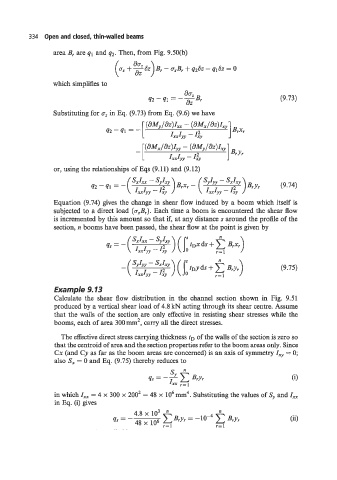
Example 9.13
Calculate the shear flow distribution in the channel section shown in Fig. 9.51
produced by a vertical shear load of 4.8 kN acting through its shear centre. Assume
that the walls of the section are only effective in resisting shear stresses while the
booms, each of area 300mm2, carry all the direct stresses.
The effective direct stress carrying thickness tD of the walls of the section is zero so
that the centroid of area and the section properties refer to the boom areas only. Since
Cx (and Cy as far as the boom areas are concerned) is an axis of symmetry Ixy = 0;
also Sx = 0 and Eq. (9.75) thereby reduces to
in which Ixx = 4 x 300 x 2002 = 48 x lo6 mm4. Substituting the values of S, and I,,
in Eq. (i) gives
(ii)