
Page 357 - Aircraft Stuctures for Engineering Student
P. 357
338 Open and closed, thin-walled beams
Substituting for q12 from Eq. (9.78) gives
9.9.3 Shear loading of closed section beams
p_
Arguments identical to those in the shear of open section beams apply in this case.
Thus, the shear flow at any point around the cross-section of a closed section beam
comprising booms and skin of direct stress carrying thickness tD is, by a comparison
of Eqs (9.75) and (9.35)
Note that the zero value of the ‘basic’ or ‘open section’ shear flow at the ‘cut’ in a skin
for which tD = 0 extends from the ‘cut’ to the adjacent booms.
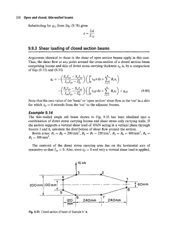
Example 9.14
The thin-walled single cell beam shown in Fig. 9.55 has been idealized into a
combination of direct stress carrying booms and shear stress only carrying walls. If
the section supports a vertical shear load of 10 kN acting in a vertical plane through
booms 3 and 6, calculate the distribution of shear flow around the section.
2
2
2
Boom areas: B1 = Bs = 200mm B2 = 8, = 250mm B3 = Bs = 400mm , B4 =
B5 = loom2.
The centroid of the direct stress carrying area lies on the horizontal axis of
symmetry so that Ixy = 0. Also, since tD = 0 and only a vertical shear load is applied,
t ’O kN
n
120 240mm - ~ 240mm ~
- mmt+
Fig. 9.55 Closed section of beam of Example 9.14.