
Page 360 - Aircraft Stuctures for Engineering Student
P. 360
9.9 Effect of idealization 341
n
N
P
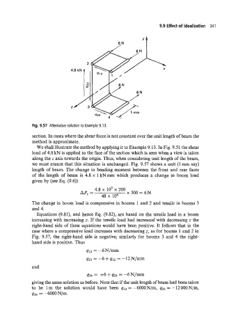
Fig. 9.57 Alternative solution to Example 9.13.
section. In cases where the shear force is not constant over the unit length of beam the
method is approximate.
We shall illustrate the method by applying it to Example 9.13. In Fig. 9.51 the shear
load of 4.8 kN is applied to the face of the section which is seen when a view is taken
along the z axis towards the origin. Thus, when considering unit length of the beam,
we must ensure that this situation is unchanged. Fig. 9.57 shows a unit (1 mm say)
length of beam. The change in bending moment between the front and rear faces
of the length of beam is 4.8 x 1 kNmm which produces a change in boom load
given by (see Eq. (9.6))
4.8 io3 200 3oo = 6N
AP, =
48 x lo6
The change in boom load is compressive in booms 1 and 2 and tensile in booms 3
and 4.
Equations (9.81), and hence Eq. (9.82), are based on the tensile load in a boom
increasing with increasing z. If the tensile load had increased with decreasing c the
right-hand side of these equations would have been positive. It follows that in the
case where a compressive load increases with decreasing z, as for booms 1 and 2 in
Fig. 9.57, the right-hand side is Eegative; similarly for booms 3 and 4 the right-
hand side is positive. Thus
q12 = -6N/=
q23 = -6 + q12 = -12N/mm
and
q34 = +6 + q23 = -6N/mm
giving the same solution as before. Note that if the unit length of beam had been taken
to be 1 m the solution would have been q12 = -6000N/m, q23 = -12000N/m,