
Page 365 - Aircraft Stuctures for Engineering Student
P. 365
346 Open and closed, thin-walled beams
Derive expressions for the vertical and horizontal components of the deflection of
the beam midway between the supports B and D. The wall thickness t and Young’s
modulus E are constant throughout.
Ans. u = 0.186W13/Ea3t, v = 0.177Wl3/Ea3t.
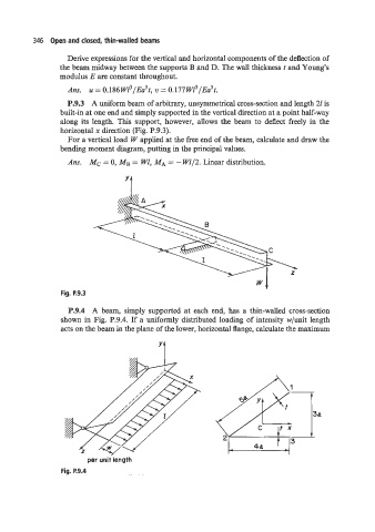
P.9.3 A uniform beam of arbitrary, unsymmetrical cross-section and length 21 is
built-in at one end and simply supported in the vertical direction at a point half-way
along its length. This support, however, allows the beam to deflect freely in the
horizontal x direction (Fig. P.9.3).
For a vertical load W applied at the free end of the beam, calculate and draw the
bending moment diagram, putting in the principal values.
Ans. Mc = 0, MB = WI, MA = - W1/2. Linear distribution.
Yt
wl
Fig. P.9.3
P.9.4 A beam, simply supported at each end, has a thin-walled cross-section
shown in Fig. P.9.4. If a uniformly distributed loading of intensity w/unit length
acts on the beam in the plane of the lower, horizontal flange, calculate the maximum
’t
per unitlength
Fig. P.9.4