
Page 351 - Aircraft Stuctures for Engineering Student
P. 351
332 Open and closed, thin-walled beams
- 1
600
4 I
600 v
6tt- I
-
I200 mm
I I40
C.' X
-
640 640 Y
0 .) 144
3
850
640 9-8
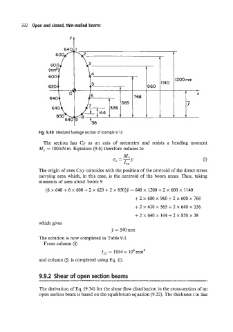
Fig. 9.49 Idealized fuselage section of Example 9.12.
The section has Cy as an axis of symmetry and resists a bending moment
M, = 100 kN m. Equation (9.6) therefore reduces to
The origin of axes Cxy coincides with the position of the centroid of the direct stress
carrying area which, in this case, is the centroid of the boom areas. Thus, taking
moments of area about boom 9
(6 x 640 + 6 x 600 f2 x 620 + 2 x 850)J = 640 x 1200 + 2 x 600 x 1140
+2 x 600 x 960+2 x 600 x 768
+2x620~565+2~640~336
+2 x 640 x 144+2 x 850 x 38
which gives
J = 540mm
The solution is now completed in Table 9.1.
From column @
I,, = 1854 x 106mm4
and column 0 is completed using Eq. (i).
9.9.2 Shear of open section beams
-III-lll*-,-,-*---X.-~~-~-~~"~-"--~--~I-1II.L.-I*~X
The derivation of Eq. (9.34) for the shear flow distribution in the cross-section of an
open section beam is based on the equilibrium equation (9.22). The thickness r in this