Page 457 - Aircraft Stuctures for Engineering Student
P. 457

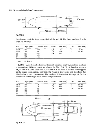
438  Stress analysis of aircraft components

                                                          2

                    304                          TI                   f             mm

                                                           I            1-     I


                                               762 mm        508 mm

                 Fig. P.10.12
                 the distance xs of the shear centre S aft of the web 34. The shear modulus G is the
                  same for all walls.

                 Wall    Length (mm)   Thickness (mm)   Boom   Area (mm2)   Cell   Area (mm’)
                  12, 56   510         0.559          1,6     645         I       93 000
                 23,45    165          0.915          2, 5    1290        I1     258 000
                  34:    1015          0.559          3,4     1935
                  38      304          2.030
                  25      304          1.625
                   Ans.  241.4mm.

                   P.10.13  A portion of a tapered, three-cell wing has singly symmetrical idealized
                  cross-sections  1OOOmm  apart  as  shown  in  Fig.  P.10.13.  A  bending  moment
                  M, = 1800 N m and a shear load Sy = 12 000 N in the plane of the web 52 are applied
                  at the larger cross-section. Calculate the forces in  the booms and the shear flow
                  distribution at this cross-section. The modulus G is constant throughout. Section
                  dimensions at the larger cross-section are given below.


                  Wall   Length (mm)   Thickness (mm)   Boom   Area (mm2)   Cell   Area (mm’)
                  12, 56   600         1 .o           1,6     600         I      100000
                  23,45   800          1 .o           2,  5   800         I1     260 000
                  34:     1200         0.6            3, 4    800         111    180000
                  3 4l    320          2.0
                  25      320          2.0
                  16      210          1.5


                       E                                                            E
                       E                                                            E
                      0 --                                                          0
                      (u                                                            (u


                                     I-    790 mm       \, 590mm  A

                  Fig. P.10.13
   452   453   454   455   456   457   458   459   460   461   462