
Page 453 - Aircraft Stuctures for Engineering Student
P. 453
434 Stress analysis of aircraft components
X
m
6
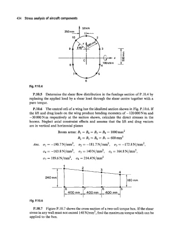
Fig. P.10.4
P.10.5 Determine the shear flow distribution in the fuselage section of P.10.4 by
replacing the applied load by a shear load through the shear centre together with a
pure torque.
P.10.6 The central cell of a wing has the idealized section shown in Fig. P.10.6. If
the lift and drag loads on the wing produce bending moments of - 120 000 Nm and
-30000Nm respectively at the section shown, calculate the direct stresses in the
booms. Neglect axial constraint effects and assume that the lift and drag vectors
are in vertical and horizontal planes
Boom areas: B1 = B4 = B5 = B8 = 1OOOmm 2
B2 = B3 = B6 = B7 = 600mm2
AFZS. ~1 = -190.7N/m2, 02 = -181.7N/mm2, 63 = -172.8N/mm2,
U4 = -163.8 N/lIUll2, 65 = 14ON/mI'Il2, 66 = 164.8 N/Inm2,
U7 = 189.6N/m2, Us = 214.4N/m2
~ 400 mm - - 400 rnrn . . 400 mm
Fig. P.10.6
P.10.7 Figure P. 10.7 shows the cross-section of a two-cell torque box. If the shear
stress in any wall must not exceed 140 N/m2, find the maximum torque which can be
applied to the box.