
Page 555 - Aircraft Stuctures for Engineering Student
P. 555
536 Matrix methods of structural analysis
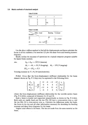
Table P.12.5(i)
Node X Y z
2 0 0 0
3 L 0 0
I L 0.8L 0
9 L 0 L
Table P.12.5(ii)
Bending Torsional
23 - EI -
37 - - GJ = 0.8EI
EI
29 EA = 6fi- - -
L=
Use the direct stzrness method to find all the displacements and hence calculate the
forces in all the members. For member 123 plot the shear force and bending moment
diagrams.
Briefly outline the sequence of operations in a typical computer program suitable
for linear frame analysis.
Ans. S29 = S28 = AP/6 (tension)
M3 = -MI = PL/9 (hogging), M2 = 2PL/9 (sagging)
SF12 = -SF23 = P/3
Twisting moment in 37, PL/18 (anticlockwise).
P.12.6 Given that the force-displacement (stiffness) relationship for the beam
element shown in Fig. P.12.6(a) may be expressed in the following form:
obtain the force-displacement (stiffness) relationship for the variable section beam
(Fig. P.12.6(b)), composed of elements 12, 23 and 34.
Such a beam is loaded and supported symmetrically as shown in Fig. P.12.6(c).
Both ends are rigidly fixed and the ties FB, CH have a cross-section area al and
the ties EB, CG a cross-section area q. Calculate the deflections under the loads,
the forces in the ties and all other information necessary for sketching the bending
moment and shear force diagrams for the beam.
Neglect axial effects in the beam. The ties are made from the same material as the
beam.