
Page 554 - Aircraft Stuctures for Engineering Student
P. 554
Problems 535
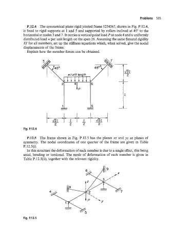
P.12.4 The symmetrical plane rigid jointed frame 1234567, shown in Fig. P.12.4,
is fixed to rigid supports at 1 and 5 and supported by rollers inclined at 45" to the
horizontal at nodes 3 and 7. It carries a vertical point load P at node 4 and a uniformly
distributed load w per unit length on the span 26. Assuming the same flexural rigidity
EI for all members, set up the stiffness equations which, when solved, give the nodal
displacements of the frame.
Explain how the member forces can be obtained.
2 z z
Fig. P.12.4
P.12.5 The frame shown in Fig. P.12.5 has the planes xz and yz as planes of
symmetry. The nodal coordinates of one quarter of the frame are given in Table
P.12.5(i).
In this structure the deformation of each member is due to a single effect, this being
axial, bending or torsional. The mode of deformation of each member is given in
Table P. 12.5(ii), together with the relevant rigidity.
Fig. P.12.5