
Page 62 - Aircraft Stuctures for Engineering Student
P. 62
2.6 Bending of an end-loaded cantilever 47
and, from Eq. (viii)
PI2 Pb2
D=---
2EI 8IG
Substitution for the constants C, D, F and H in Eqs (ix) and (x) now produces the
equations for the components of displacement at any point in the beam. Thus
u=---- (xi)
+-
vPxy2 Px3 P12x PI3
v= - (xii)
+---
2EI 6EI 2EI 3EI
The deflection curve for the neutral plane is
px3 PI^^ pi3
b)y=O =E-=+= (xiii)
from which the tip deflection (x = 0) is P13/3EI. This value is that predicted by simple
beam theory (Section 9.1) and does not include the contribution to deflection of the
shear strain. This was eliminated when we assumed that the slope of the neutral plane
at the built-in end was zero. A more detailed examination of this effect is instructive.
The shear strain at any point in the beam is given by Eq. (vi)
P
(b2
yxy = - - - 4y2)
8ZG
and is obviously independent of x. Therefore at all points on the neutral plane the
shear strain is constant and equal to
Pb2
y =--
xy 8IG
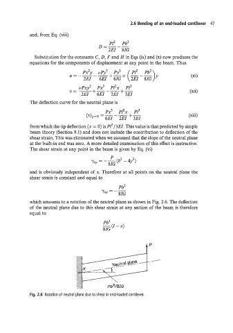
which amounts to a rotation of the neutral plane as shown in Fig. 2.6. The deflection
of the neutral plane due to this shear strain at any section of the beam is therefore
equal to
Pb2
-(I-X)
8IG
Fig. 2.6 Rotation of neutral plane due to shear in end-loaded cantilever.