
Page 63 - Aircraft Stuctures for Engineering Student
P. 63
-. r/r -;g--.-.
48 Two-dimensional problems in elasticity
P b2/8 I G
I
~
L - - - - .- - -
(a) (b)
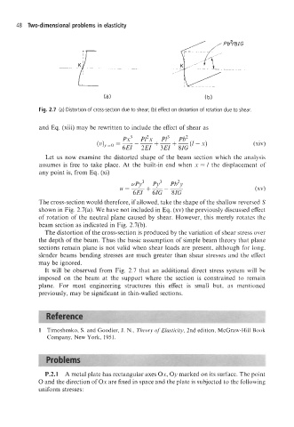
Fig. 2.7 (a) Distortion of cross-section due to shear; (b) effect on distortion of rotation due to shear.
and Eq. (xiii) may be rewritten to include the effect of shear as
Px3 P12x PI3 Pb2
(zl)y=o = 6EI - E + - + - (1 - x) (xiv)
3EI 8IG
Let us now examine the distorted shape of the beam section which the analysis
assumes is free to take place. At the built-in end when x = 1 the displacement of
any point is, from Eq. (xi)
vPy3 +--- Py3 Pb2y
u=-
6EI 61G 8IG
The cross-section would therefore, if allowed, take the shape of the shallow reversed S
shown in Fig. 2.7(a). We have not included in Eq. (xv) the previously discussed effect
of rotation of the neutral plane caused by shear. However, this merely rotates the
beam section as indicated in Fig. 2.7(b).
The distortion of the cross-section is produced by the variation of shear stress over
the depth of the beam. Thus the basic assumption of simple beam theory that plane
sections remain plane is not valid when shear loads are present, although for long,
slender beams bending stresses are much greater than shear stresses and the effect
may be ignored.
It will be observed from Fig. 2.7 that an additional direct stress system will be
imposed on the beam at the support where the section is constrained to remain
plane. For most engineering structures this effect is small but, as mentioned
previously, may be significant in thin-walled sections.
1 Timoshenko, S. and Goodier, J. N., Theory of Elasticity, 2nd edition, McGraw-Hill Book
Company, New York, 1951.
P.2.1 A metal plate has rectangular axes Ox, Oy marked on its surface. The point
0 and the direction of Ox are fixed in space and the plate is subjected to the following
uniform stresses: