
Page 154 -
P. 154
128 Chapter 3 ■ Digital Morphology
3.4.3 Gradient
In Section 3.2.8 a method for identifying the boundaries of a bi-level object was
discussed. The basic idea was to erode an image using the simple structuring
element and then subtract the result from the original, leaving only the pixels
that were eroded. This can be done with grey-level images too. The boundary
detectionoperatorcan be expressed inthe same manner asinEquation3.14,
and results in an operation not unlike unsharp masking, in which an average of
a small (say, 3x3) region is subtracted from the original pixel at the center of
the region. This procedure has an analog in photography.
Because the contrast is not as great in a grey-level image as in a bi-level
one the results of the boundary detection are not as good. However, an
improvement can be achieved by using the formula:
G = (A ⊕ S) − (A S) (EQ 3.32)
where S is a structuring element. Instead of subtracting the eroded image from
the original, Equation 3.32 subtracts it from a dilated image. This increases
the contrast and width of the extracted edges. Equation 3.32 is the definition
of the morphological gradient, which detects edges in a manner that is
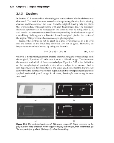
less dependant on direction than is the usual gradient operator. Figure 3.30
shows both the boundary detection algorithm and the morphological gradient
applied to the disk guard image. In all cases, the simple structuring element
was used.
(a) (b)
(c) (d)
Figure 3.30: Morphological gradient. (a) Disk guard image. (b) Edges enhanced by the
grey-level boundary extraction method applied to grey-level images, then thresholded. (c)
The morphological gradient. (d) Image (c) after thresholding.