
Page 124 - Alternative Energy Systems in Building Design
P. 124
100 SOLAR POWER SYSTEM PHYSICS AND TECHNOLOGIES
ROOF STAND
TOP VIEW TOP VIEW
SOLAR PANEL
BOLT DOWN
LAG SCREW
SUPPORT RAILING
GROUTING
COMPOUND
ROOF STRUCTURE
(a)
TOP VIEW ROOF STAND TOP VIEW
JUNCTION
BOX BOLT DOWN
SOLAR PANEL LAG SCREW
SUPPORT
TROUGH GROUTING
BOLT AND NUT COMPOUND
REDWOOD RUNNER ROOF STRUCTURE
BOLT DOWN
LAG SCREW
(b)
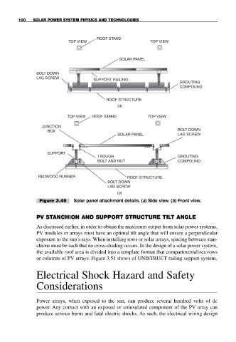
Figure 3.49 Solar panel attachment details. (a) Side view. (b) Front view.
PV STANCHION AND SUPPORT STRUCTURE TILT ANGLE
As discussed earlier, in order to obtain the maximum output from solar power systems,
PV modules or arrays must have an optimal tilt angle that will ensure a perpendicular
exposure to the sun’s rays. When installing rows or solar arrays, spacing between stan-
chions must be such that no cross-shading occurs. In the design of a solar power system,
the available roof area is divided into a template format that compartmentalizes rows
or columns of PV arrays. Figure 3.51 shows of UNISTRUCT railing support system.
Electrical Shock Hazard and Safety
Considerations
Power arrays, when exposed to the sun, can produce several hundred volts of dc
power. Any contact with an exposed or uninsulated component of the PV array can
produce serious burns and fatal electric shocks. As such, the electrical wiring design