
Page 207 - Alternative Energy Systems in Building Design
P. 207
COMPUTERIZED LIGHTING CONTROL 183
Daylit Daylit
dimming –iPC-L dimming
–iPC-L zone Local zone
dim 4 photosensor
dim 3 General
lighting zone
Hot dim 2 General lighting zone
dim 1
MicroPanel-iDim
Digital switch (local and global control)
Daylit Daylit -iPC-G
dimming dimming Global PCCI
zone zone Daylit zone photosensor Daylit zone
“c” leg “c” leg
dim 4
dim 3
Hot dim 2 General “b” leg “b” leg
dim 1 General lighting zone “a” leg “a” leg
lighting zone
MicroPanel-iDim MicroPanel-iDH MicroPanel-iDH
Digital switch (local and global control)
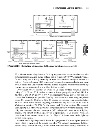
Figure 5.3 Centralized dimming and lighting-control diagram. Courtesy of LCD.
32 to 64 addressable relay channels, 365-day programmable astronomical timers, tele-
communications modems, mixed-voltage output relays (120–277 V), manual override
for each relay, and a linkup capability of more than 100 links to digital devices via
Category 5 patch cables and RJ45 connectors. The preceding systems also include smart
breaker panels that use solenoid-operated thermal magnetic breakers that effectively
provide overcurrent protection as well as lighting control.
Overcurrent devices usually are available in single or three phases; a current
rating of 15, 20, and 30 A; and an arc current interrupt capacity (AIC) of 14 kA at
120/208 V and 65 kA at 277/480 V. A microprocessor-based current-limiting sub-
branch distribution panel provides lighting calculations for most energy-regulated
codes. For example, California Title 24 energy compliance requirements dictate
45 W of linear power for track lighting, whereas the city of Seattle in the state of
Washington requires 70 W/ft for the same track lighting system. The current-
limiting subpanel effectively provides a programmable circuit current-limiting capa-
bility that lowers or raises the voltampere (VA) rating requirement for track lighting
circuits. The current-limiting capacity for a typical panel is 20 circuits; with each
capable of limiting current from 1 to 15 A. Figure 5.4 shows some of the lighting-
control components.
Another useful lighting-control device is a programmable zone lighting-control
panel, which is capable of the remote control of 512 uniquely addressable lighting-
control relays. Groups of relays can be either controlled individually, referred to as