
Page 208 - Alternative Energy Systems in Building Design
P. 208
184 ENERGY CONSERVATION
Occ.sensor Phaser
-iPC-L -iPC-L
Relay panel
Digital switch Slider switch
Slider switch
iDim
Micro phaser
Computer
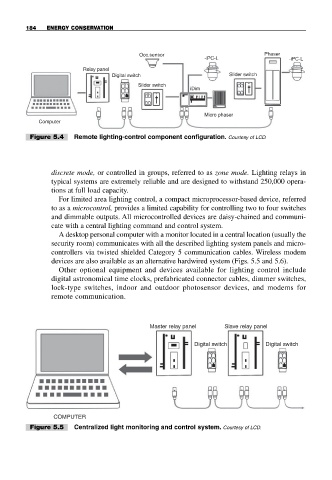
Figure 5.4 Remote lighting-control component configuration. Courtesy of LCD.
discrete mode, or controlled in groups, referred to as zone mode. Lighting relays in
typical systems are extremely reliable and are designed to withstand 250,000 opera-
tions at full load capacity.
For limited area lighting control, a compact microprocessor-based device, referred
to as a microcontrol, provides a limited capability for controlling two to four switches
and dimmable outputs. All microcontrolled devices are daisy-chained and communi-
cate with a central lighting command and control system.
A desktop personal computer with a monitor located in a central location (usually the
security room) communicates with all the described lighting system panels and micro-
controllers via twisted shielded Category 5 communication cables. Wireless modem
devices are also available as an alternative hardwired system (Figs. 5.5 and 5.6).
Other optional equipment and devices available for lighting control include
digital astronomical time clocks, prefabricated connector cables, dimmer switches,
lock-type switches, indoor and outdoor photosensor devices, and modems for
remote communication.
Master relay panel Slave relay panel
Digital switch Digital switch
COMPUTER
Figure 5.5 Centralized light monitoring and control system. Courtesy of LCD.