
Page 162 - Amphibionics : Build Your Own Biologically Inspired Robot
P. 162
Amphibionics 05 3/24/03 8:44 AM Page 141
Chapter 5 / Serpentronic: Build Your Own Robotic Snake
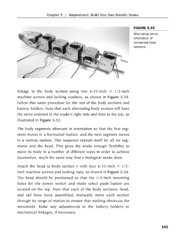
FIGURE 5.33
Alternating servo
orientation of
connected body
sections.
linkage to the body section using two 6/32-inch 1/2-inch
machine screws and locking washers, as shown in Figure 5.32.
Follow this same procedure for the rest of the body sections and
battery holders. Note that each alternating body section will have
the servo oriented to the snake’s right side and then to the top, as
illustrated in Figure 5.33.
The body segments alternate in orientation so that the first seg-
ment moves in a horizontal motion, and the next segment moves
in a vertical motion. This sequence repeats itself for all six seg-
ments and the head. This gives the snake enough flexibility to
move its body in a number of different ways in order to achieve
locomotion, much the same way that a biological snake does.
Attach the head to body section 1 with four 6/32-inch 1/2-
inch machine screws and locking nuts, as shown in Figure 5.34.
The head should be positioned so that the 1/4-inch mounting
holes for the power switch and mode select push button are
located on the top. Now that each of the body sections, head,
and tail have been assembled, manually move each section
through its range of motion to ensure that nothing obstructs the
movement. Make any adjustments to the battery holders or
mechanical linkages, if necessary.
141