
Page 49 - Amphibionics : Build Your Own Biologically Inspired Robot
P. 49
Amphibionics 03 3/24/03 8:11 AM Page 28
Amphibionics
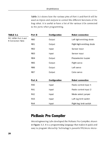
Table 3.1 shows how the various pins of Port A and Port B will be
used as inputs and outputs to control the different functions of the
frog robot. It is useful to have a list of the various I/Os connected
to the ports when programming.
TABLE 3.1 Port B Configuration Robot connection
PIC 16F84 Port A and
RB0 Output Left light-emitting diode
B Connection Table
RB1 Output Right light-emitting diode
RB2 Input Sensor input
RB3 Input Sensor input
RB4 Output Piezoelectric buzzer
RB5 Output Right servo
RB6 Output Left servo
RB7 Output Extra servo
Port A Configuration Robot connection
RA0 Input Radio control input 1
RA1 Input Radio control input 2
RA2 Input Mode select jumper
RA3 Input Left leg limit switch
RA4 Input Right leg limit switch
PicBasic Pro Compiler
MicroEngineering Labs developed the PicBasic Pro Compiler, shown
in Figure 3.3. It is a programming language that makes it quick and
easy to program Microchip Technology’s powerful PICmicro micro-
28