
Page 107 - An Introduction to Analytical Atomic Spectrometry - L. Ebdon
P. 107
Page 90
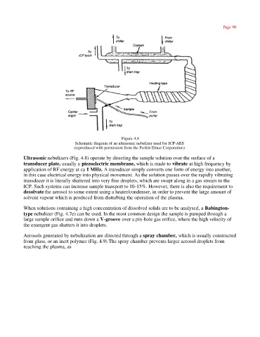
Figure 4.8
Schematic diagram of an ultrasonic nebulizer used for ICP-AES
(reproduced with permission from the Perkin Elmer Corporation).
Ultrasonic nebulizers (Fig. 4.8) operate by directing the sample solution over the surface of a
transducer plate, usually a piezoelectric membrane, which is made to vibrate at high frequency by
application of RF energy at ca 1 MHz. A transducer simply converts one form of energy into another,
in this case electrical energy into physical movement. As the solution passes over the rapidly vibrating
transducer it is literally shattered into very fine droplets, which are swept along in a gas stream to the
ICP. Such systems can increase sample transport to 10-15%. However, there is also the requirement to
desolvate the aerosol to some extent using a heater/condenser, in order to prevent the large amount of
solvent vapour which is produced from disturbing the operation of the plasma.
When solutions containing a high concentration of dissolved solids are to be analysed, a Babington-
type nebulizer (Fig. 4.7e) can be used. In the most common design the sample is pumped through a
large sample orifice and runs down a V-groove over a pin-hole gas orifice, where the high velocity of
the emergent gas shatters it into droplets.
Aerosols generated by nebulization are directed through a spray chamber, which is usually constructed
from glass, or an inert polymer (Fig. 4.9) The spray chamber prevents larger aerosol droplets from
reaching the plasma, as