
Page 135 - An Introduction to Analytical Atomic Spectrometry - L. Ebdon
P. 135
Page 119
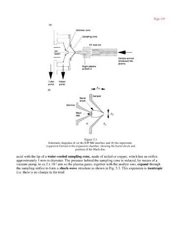
Figure 5.3
Schematic diagrams of (a) the ICP-MS interface and (b) the supersonic
expansion formed in the expansion chamber, showing the barrel shock and
position of the Mach disc.
axial with the tip of a water-cooled sampling cone, made of nickel or copper, which has an orifice
approximately 1 mm in diameter. The pressure behind the sampling cone is reduced, by means of a
vacuum pump, to ca 2 x 10 atm so the plasma gases, together with the analyte ions, expand through
-3
the sampling orifice to form a shock-wave structure as shown in Fig. 5.3. This expansion is isentropic
(i.e. there is no change in the total