
Page 141 - An Introduction to Analytical Atomic Spectrometry - L. Ebdon
P. 141
Page 125
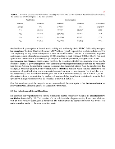
Table 5.1 Common spectroscopic interferences caused by molecular ions, and the resolution that would be necessary to separate
the analyte and interference peaks in the mass spectrum.
Analyte ion Interfering ion
Nominal Accurate Nominal Accurate Resolution
isotope m/z isotopes m/z required
35
51 V 50.9405 16 O Cl 50.9637 2580
16
56 Fe 55.9349 40Ar O 55.9572 2510
23
63 Cu 62.9295 40 Ar Na 62.9521 2778
35
75 As 74.9216 40 Ar CI 74.9312 7771
obtainable with quadrupoles is limited by the stabiliy and uniformity of the RF/DC field and by the spread in
ion energies of the ions. Quadrupoles used in ICP-MS are typically operated at resolutions between 12 and
350, depending on m/z, which corresponds to peak widths between 0.7 and 0.8. In comparison, magnetic
sectors are capable of resolution exceeding 10 000, resulting in peak widths of 0.008 at 80 m/z. For most
applications the resolution provided by a quadrupole is sufficient; however, for applications when
spectroscopic interferences cause a major problem, the resolution afforded by a magnetic sector may be
desirable. Table 5.1 gives examples of some common spectroscopic interferences that may be encountered
(see Section 5.6) and the resolution required to separate the element of interest from the interference. For
example, a particular problem is the determination of arsenic in a matrix which contains chloride (a common
component of most biological or environmental samples). Arsenic is monoisotopic (i.e. it only has one
isotope) at m/z 75 and the chloride matrix gives rise to an interference at m/z 75 due to Ar Cl , so an
+
35
40
alternative isotope is not available for analysis. A quadrupole has insufficient resolution to separate the two
species but a magnetic sector could do so easily, as shown in Table 5.1.
One further advantage of the magnetic sector compared with the quadrupole is that ion transmission, and
hence sensitivity, are much greater for comparable resolution.
5.5 Ion Detection and Signal Handling.
Ion detection can be perfomed by a variety of methods, but the commonest by far is the channel electron
multiplier shown in Fig. 5.8. This consists of a curved glass tube of approximately 1 mm internal diameter
with an inner resistive coating and a flared end. The multiplier can be operated in one of two modes. In the
pulse counting mode — the most sensitive mode