
Page 142 - An Introduction to Analytical Atomic Spectrometry - L. Ebdon
P. 142
Page 126
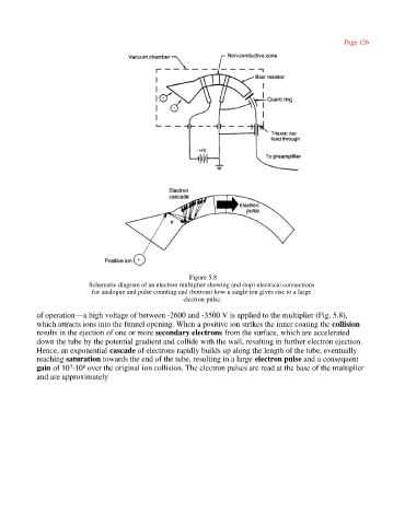
Figure 5.8
Schematic diagram of an electron multiplier showing and (top) electrical connections
for analogue and pulse counting and (bottom) how a single ion gives rise to a large
electron pulse.
of operation—a high voltage of between -2600 and -3500 V is applied to the multiplier (Fig. 5.8),
which attracts ions into the funnel opening. When a positive ion strikes the inner coating the collision
results in the ejection of one or more secondary electrons from the surface, which are accelerated
down the tube by the potential gradient and collide with the wall, resulting in further electron ejection.
Hence, an exponential cascade of electrons rapidly builds up along the length of the tube, eventually
reaching saturation towards the end of the tube, resulting in a large electron pulse and a consequent
gain of 10 -10 over the original ion collision. The electron pulses are read at the base of the multiplier
7
8
and are approximately