
Page 212 - An Introduction to Microelectromechanical Systems Engineering
P. 212
Passive Electrical Components: Capacitors and Inductors 191
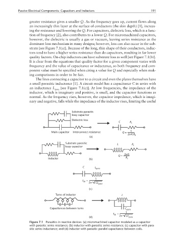
greater resistance gives a smaller Q. As the frequency goes up, current flows along
an increasingly thin layer at the surface of conductors (the skin depth) [1], increas-
ing the resistance and lowering the Q. For capacitors, dielectric loss, which is a func-
tion of frequency [2], also contributes to a lower Q. For micromachined capacitors,
however, the dielectric is usually a gas or vacuum, leaving series resistance as the
dominant loss mechanism in many designs; however, loss can also occur in the sub-
strate [see Figure 7.1(a)]. Because of the long, thin shape of their conductors, induc-
tors tend to have a higher series resistance than do capacitors, resulting in far lower
quality factors. On-chip inductors can have substrate loss as well [see Figure 7.1(b)].
It is clear from the equations that quality factor for a given component varies with
frequency and the value of capacitance or inductance, so both frequency and com-
ponent value must be specified when citing a value for Q and especially when mak-
ing comparisons in order to be fair.
The lines connecting a capacitor to a circuit and even the plates themselves have
a small parasitic inductance [1]. A circuit model has a capacitance C in series with
an inductance L [see Figure 7.1(c)]. At low frequencies, the impedance of the
para
inductor, which is imaginary and positive, is small, and the capacitor functions as
normal. As the frequency rises, however, the capacitor impedance, which is imagi-
nary and negative, falls while the impedance of the inductor rises, limiting the useful
Substrate parasitic
lossy capacitor
Dielectric loss
C R s
Main capacitor Interconnect resistance Q = 1
2πfCR s
(a)
Substrate parasitic L R
lossy capacitor s
2πfL
Q =
Inductor (b) R s
C L para
1
f SR = 2π CL para
(c)
Turns of inductor L
Capacitances between turns C
para
1
f SR =
(d) 2π LC para
Figure 7.1 Parasitics in reactive devices: (a) micromachined capacitor modeled as a capacitor
with parasitic series resistance; (b) inductor with parasitic series resistance; (c) capacitor with para-
sitic series inductance; and (d) inductor with parasitic parallel capacitance between coils.