
Page 214 - An Introduction to Microelectromechanical Systems Engineering
P. 214
Passive Electrical Components: Capacitors and Inductors 193
bulk-micromachined counterparts, but they have a nonlinear response to the tun-
ing voltage and smaller tuning ranges. The quality factor and self-resonance fre-
quency vary with the design.
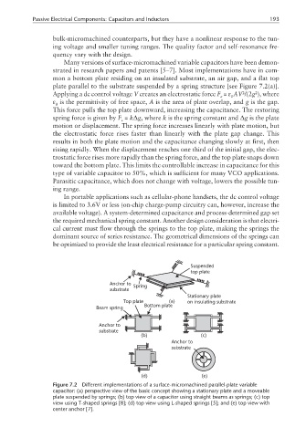
Many versions of surface-micromachined variable capacitors have been demon-
strated in research papers and patents [5–7]. Most implementations have in com-
mon a bottom plate residing on an insulated substrate, an air gap, and a flat top
plate parallel to the substrate suspended by a spring structure [see Figure 7.2(a)].
2
2
Applying a dc control voltage V creates an electrostatic force F = ε AV /(2g ), where
e 0
ε is the permittivity of free space, A is the area of plate overlap, and g is the gap.
0
This force pulls the top plate downward, increasing the capacitance. The restoring
spring force is given by F = k∆g, where k is the spring constant and ∆g is the plate
s
motion or displacement. The spring force increases linearly with plate motion, but
the electrostatic force rises faster than linearly with the plate gap change. This
results in both the plate motion and the capacitance changing slowly at first, then
rising rapidly. When the displacement reaches one third of the initial gap, the elec-
trostatic force rises more rapidly than the spring force, and the top plate snaps down
toward the bottom plate. This limits the controllable increase in capacitance for this
type of variable capacitor to 50%, which is sufficient for many VCO applications.
Parasitic capacitance, which does not change with voltage, lowers the possible tun-
ing range.
In portable applications such as cellular-phone handsets, the dc control voltage
is limited to 3.6V or less (on-chip charge-pump circuitry can, however, increase the
available voltage). A system-determined capacitance and process-determined gap set
the required mechanical spring constant. Another design consideration is that electri-
cal current must flow through the springs to the top plate, making the springs the
dominant source of series resistance. The geometrical dimensions of the springs can
be optimized to provide the least electrical resistance for a particular spring constant.
Suspended
top plate
Anchor to Spring
substrate
Stationary plate
Top plate (a) on insulating substrate
Bottom plate
Beam spring
Anchor to
substrate
(b) (c)
Anchor to
substrate
(d) (e)
Figure 7.2 Different implementations of a surface-micromachined parallel-plate variable
capacitor: (a) perspective view of the basic concept showing a stationary plate and a moveable
plate suspended by springs; (b) top view of a capacitor using straight beams as springs; (c) top
view using T-shaped springs [8]; (d) top view using L-shaped springs [5]; and (e) top view with
center anchor [7].