
Page 45 - Analog Circuit Design Art, Science, and Personalities
P. 45
On Being the Machine
Having considered a solution to a problem that existed over four decades ago and
recognizing what may now appear lo be an obvious solution, the reader may be
inclined to shrug and say, “So what?” But recall that major engineering efforts,
based on what was, at the time, the obvious brute-force approach were expended by
highly competent engineers before the more apparently sophisticated, but actually
simpler, approach based on broader considerations and visceral recognition was
brought to bear.
Consider now another example, perhaps somewhat more complex, related to the
development, in the early 1970s, of what were then called “Computer Assisted
Tomography” systems, which today are known as CAT scanners. In one generation
of these systems (later the most popular called “Fan Beam Rotate-Rotate” machines),
a multiplicity of detectors, indeed many hundreds, simultaneously convert impinging
X-ray photons into low-level currents on the order of a few hundred nanoamperes
full scale. In order to be able to compute a high-quality image with great detail and
minimum artifacts, it is necessary to integrate and measure these currents over a
dynamic range of one million to one and with every channel tracking every one of
the hundreds of other channels to within a few parts in a million over that entire
range. Experienced analog engineers will recognize this requirement to be a formid-
able task.
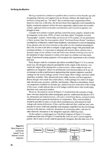
Early designs made by competent specialists resembled Figure 5-4. In a conven-
tional way, the designers placed a preamplifier at the output of the detector, con-
verted the output of the preamp into a current source, whose output in turn was
applied to an integrator, which was periodically reset between pulses of X-ray. In
an attempt to achieve performance approaching that needed, engineers searched
catalogs for the lowest leakage current, lowest input offset voltage, and most stable
ampli tiers available. They obtained the most stable resistors and best capacitors.
But no designs were made that could achieve, within perhaps two orders of magni-
tude, the necessary accuracy, stability, and linearity. Objective calculations, based
on components available two decades ago. indeed even now at the time of the writing
of this essay, would indicate that no error budget could be drawn that would imply
that there was a practical solution.
However, the practical circuit of Figure 5-5 resulted from the concepts of engi-
neers who had studied the entire tomography process, understood the physics of X-
ray attenuation and statistical noise, who knew control loop theory, and particularly
understood and accepted the limitations of components. They conceived that it
should be possible to make a circuit which simultaneously autozeroed out both
voltage and current drift errors. If this could be achieved, they could not only com-
pensate for errors within the amplifier and integrator amplifiers but also for leakage
currents in the detector, dielectric absorption in connecting cables, and also for
other dielectric absorption in the integrator capacitor, following reset.
On the surface it would appear as if the block diagram of Figure 5-5 is more
complicated than that of Figure 5-4 and that the costs for such a circuit might be
greater. But if such a circuit could be practically designed, then the total cost of its
Figure 5-4.
Block diagram of c--,+
urrent
a precision S ‘ource HintegratorB output
“pulsed” X-ray I
detector current
integrator.
26