
Page 38 - Analog and Digital Filter Design
P. 38
35
Introduction
BRICK WALL RESPONSE
1.5
W
0
’ 1-
k
J 0.5
z
a.
FREQUENCY
w 1.5 I
TI ME
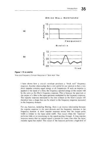
Figure 1.15 (a and b)
Time and Frequency Domain Response of “Brick Wall” Filter
I have shown how a sin(x)/s envelope produces a “brick wall” frequency
response. Another relationship that is very useful for our analysis is that a very
short impulse contains equal energy at all frequencies. If such an impulse is
applied to the input of a filter, the frequency spectral energy at the output will
be the same as the filter’s frequency response. This is because the spectrum at
the output of a filter is the input spectrum multiplied by the frequency response.
The impulse response measured in the time domain at the filter’s output will
therefore have a shape that can be related to the frequency response measured
in the frequency domain.
For any function, including filtering, there is an inverse relationship between
the impulse response in the time domain and the frequency response in the
frequency domain. A short impulse response means that the output pulse
width is similar to the input pulse width. This occurs when the “function”
performs little or no processing on the signal passing through. A long impulse
response means that an output signal is present for some time after the input
impulse signal has ended. This occurs if the function performs a high level of