Page 37 - Analog and Digital Filter Design
P. 37

34      Analog and Digital Filter Design
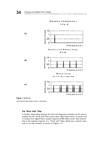


                                                    SOURCE FREQUENCY
                                                               >Fs/2


                                                  1        .       5         1        1
                                               k ’1

                                               i! 0.5
                                               :o

                                                                      FREQUENCY
                                                   SAMPLl NG SPECTRUM,
                                                               N x Fs


                                                                      FREQUENCY

                                                           SPECTRUM
                                                        WITH  ALIASING


                                                                      FREQUENCY
                  Figure 1.14 (a-c)
                  Alias Signal Generation due to Sampling


                        The  “Brick Wall” Filter
                        A further relationship between the time and frequency domains can be used to
                        explain why the “brick wall” filter cannot exist. More importantly, it can be used
                        to explain how digital finite impulse response (FIR) filters work. This relation-
                        ship is the impulse response of  a “brick wall” filter, which has a sin(x)/x enve-
                        lope in the time domain, as shown in Figure 1.15.
   32   33   34   35   36   37   38   39   40   41   42