
Page 32 - Analog and Digital Filter Design
P. 32
29
Introduction
tend to have a limited frequency range because of the integrated component
values that have been provided.
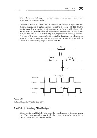
Switched capacitor IC filters use the principle of rapidly charging and dis-
charging a capacitor to replace a resistor, as shown in Figure 1.1 1. The effective
resistor value depends on the rate of switching of the charge and discharge cycle.
As the switching speed is changed, the effective resistance of the circuit also
changes. The filter can thus be tuned by changing the switch clocking frequency.
This type of filter generates signals at the switching frequency, and they tend to
be generally noisy. Most switched capacitor filters are lowpass types and are
limited in their frequency range to below 100 kHz.
b-
TC
Figure 1.11
Switched Capacitor "Resistor Equivalent"
The Path to Analog Filter Design
At this point it would be helpful to know the overall process to design an analog
filter. These processes will be described fully in later chapters, but a description
now will help put it all into perspective.