
Page 29 - Analog and Digital Filter Design
P. 29
26 Analog and Digital Filter Design
the filter is designed for zero source impedance, the filter's input voltage and the
source voltage are identical, so the voltage at the filter input is measured.
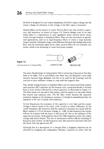
Analog filters can be passive or active. Passive filters use only resistors, capaci-
tors, and inductors, as shown in Figure 1.8. Passive designs tend to be used
where there is a requirement to pass significant direct current (above about
1 mA) through lowpass or bandstop filters. They are also used more in special-
ized applications, such as in high-frequency filters or where a large dynamic
range is needed. (Dynamic range is the difference between the background noise
floor and the maximum signal level.) Also, passive filters do not consume any
power, which is an advantage in some low-power systems.
Figure 1.8
Components of a Passive Filter CAPACITOR RES I STOR
The main disadvantage of using passive filters containing inductors is that they
tend to be bulky. This is particularly true when they are designed to pass high
currents, because large diameter wire has to be used for the windings and the
core has to have sufficient volume to cope with the magnetic flux.
Very simple analog lowpass or highpass filters can be constructed from resistor
and capacitor (RC) networks. In the lowpass case, a potential divider is formed
from a series resistor followed by a shunt capacitor, as illustrated in Figure 1.9.
The filter input is at one end of the resistor and the output is at the point where
the resistor and capacitor join. The RC filter works because the capacitor
reactance reduces as the frequency increases. It should be remembered that the
reactance is 90" out of phase with resistance.
At low frequencies the reactance of the capacitor is very high and the output
voltage is almost equal to the input, with virtually no phase difference. At the
cutoff frequency, the resistance and the capacitive reactance are equal and the
filter's output is l/fi of the input voltage, or -3 dB. At this frequency the output
will not be in phase with the input: it will lag by 45" due to the influence of the
capacitive reactance. At frequencies above the 3 dB attenuation point, the output
voltage will reduce further. The rate of attenuation will be 6 dB per doubling of
frequency (per octave). As the frequency rises, the capacitive reactance falls and
the phase shift lag approaches 90".
Although this is a description of a lowpass filter, a highpass response can be
obtained by swapping the components. Placing a capacitor in series with the