
Page 25 - Analog and Digital Filter Design
P. 25
22 Analog and Digital Filter Design
The transfer function, F(w), is frequency dependent. For example, suppose that
at w- = 0.5, F(o) is equal to 1 and hence V,,, = VI,. Now suppose that at w = 2,
F(w) is equal to 0.01, hence V,,, is V,, + 100. In decibels, the gain is -40dB, since
it is 2010g(V,,,Nl,,); since the gain is negative, this can be referred to as a
(positive) attenuation, or signal loss, of 40dB. The function F(o) is flawed
because it assumes that the source and load impedance has no effect.
For the most common filter types, the transfer function is often presented in
graphical form. The graph has a number of curves showing signal gain (loss)
versus frequency. As the filter design grows more complex, the steepness of the
curve increases. This means that a design engineer can determine the simplest
filter for a given performance, by comparing one curve with another.
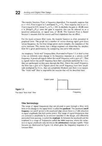
An imaginary "brick wall" lowpass filter, illustrated in Figure 1.3, is ideal in that
it has an infinitely steep change in its frequency response at a certain cutoff
frequency. It passes all signals below the cutoff frequency with a gain of 1. That
is, signals below the cutoff frequency have their amplitude multiplied by 1 (it.,
they are unchanged) as they pass through the filter. Above the cutoff frequency,
the filter has a gain of 0. Signals above the cutoff frequency have their ampli-
tude multiplied by 0 (Le., they are completely blocked) and there is no output.
The "brick wall" filter is impossible for reasons that will be described later.
Figure 1.3
The Ideal "Brick Wall" Filter Frequency
Filter Terminology
The range of signal frequencies that are allowed to pass through a filter, with
little or no change to the signal level, is called the passband. The passband cutoff
frequency (or cutoff point) is the passband edge where there is a 3 dB reduction
in signal amplitude (the half-power point). The range of signal frequencies that
are reduced in amplitude by an amount specified in the design, and effectively
prevented from passing, is called the stopband. In between the passband and the
stopband is a range of frequencies called the skirt response, where the reduc-
tion in signal amplitude (also known as the attentuation) changes rapidly. These
features are illustrated in Figure 1.4, which gives the frequency response of a
lowpass filter.