
Page 24 - Analog and Digital Filter Design
P. 24
Introduction 21
Decibels
The amplitude of a signal is measured in volts. The r.m.s. (root means square)
voltage of AC signals is used, rather than the peak voltage, because this gives
the same power as a DC signal having that voltage. However, because the signal
level has to be multiplied by the gain or loss of components (such as filters) in
the signal path, decibels are used. This make the mathematics simpler, because
once the voltage is expressed in decibel notation, gains can be added and losses
can be subtracted.
The number of decibels relative to one volt is expressed as dBV, and is given by
the expression 20 log(V). That is, measure the voltage (V), take the logarithm of
it. and multiply the result by 20. If the voltage level is 0.5 volts, this is expressed
as -6dBV. If this signal is amplified by an amplifier having a gain of 10
(+20dB), the output signal will be -6 + 20 = +14dBV.
Signal power can be expressed in decibels too. The most common unit of power
is the milliwatt, and the number of decibels relative to one milliwatt is expressed
as dBm. The formula for expressing power (P) in decibels is lOlog(P), hence
a milliwatt equals OdBm. However, the signal is measured in terms of volts
and converted to power using P = V'/R, where R is the load resistance. In filter
designs the half-power signal level (-3 dB) is often used as a reference point for
the filter's passband.
The Transfer Function
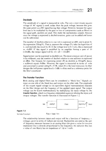
Both analog and digital filters can be considered a "black box." Signals are
input on one side of the black box and output on the other side. The amplitude
of the output signal voltage (or its equivalent digital representation) depends
on the filter design and the frequency of the applied input signal. The output
voltage can be found mathematically by multiplying the input voltage by the
transfer function, which is a frequency-dependent equation relating the input and
output voltages. The transfer function is illustrated in Figure 1.2.
r
Vin OUTPUT T Vout
r
Figure 1.2
Transfer Function F(w) = Vout I Vin
The relationship between input and output will be a function of frequency 11'
(omega), given in terms of radians per second. Radiandsec are used as the unit
of frequency measure because in an analog filter this gives a value for reactive
impedance that is directly proportional to the frequency. An inductor that has
a value of one Henry has an impedance of 1 Q at 1 rad/s.