Page 27 - Analog and Digital Filter Design
P. 27

24      Analog and Digital Filter Design


                        The designer must determine the cutoff frequencies, the stopband attenuation,
                        and whether a lowpass, highpass, bandpass, or bandstop filter is required. Some-
                        times this specification will be supplied by the system designer, but this may be
                        left to the filter designer to decide for him or herself.

                        Phase Response
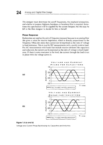
                        Radianslsec are used as the unit of frequency measure because in an analog filter
                        this gives a value for reactive impedance, which is directly proportional to the
                        frequency. Ohms law states that current can be expressed as the ratio of voltage
                        to load resistance. This is true for DC measurements with a purely resistive load.
                        For AC measurements with loads that include reactive elements like capacitors
                        and inductors, the current can be expressed as the ratio of voltage to load imped-
                        ance. If  there is some reactance in the load, the current through the load is not
                        in phase with the voltage across it.


                                                    VOLTAGE  AND  CURRENT
                                                    PHASE FOR  CAPACITORS

                                                   1
                                               w
                                               0 0.5
                                               3
                                               h  o
                                               J
                                               ; 4.5
                                               Q  -1

                                                  I."
                                                                                 TI ME
                                                -VOITAG      E-C   U RRE NT

                                                  VOLTAGE  AND  CURRENT
                                                  PHASE FOR  INDUCTORS


                                                 -1.5 1'
                                                                                TI ME
                                                                  C
                                                -VULT     AG E - u R RE N T
                  Figure 1.6 (a and b)
                  Voltage and Current Phase Relationship for Capacitors and Inductors
   22   23   24   25   26   27   28   29   30   31   32