
Page 30 - Analog and Digital Filter Design
P. 30
27
Introduction
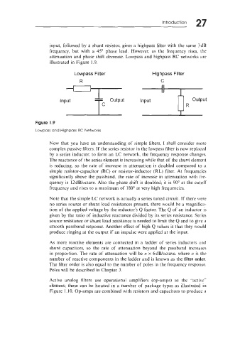
input, followed by a shunt resistor, gives a highpass filter with the same 3dB
frequency, but with a 45" phase lead. However. as the frequency rises, the
attenuation and phase shift decrease. Lowpass and highpass RC networks are
illustrated in Figure 1.9.
Lowpass Filter Highpass Filter
R C
Figure 1.9
Lowpass and Highpass RC Networks
Now that you have an understanding of simple filters, I shall consider more
complex passive filters. If the series resistor in the lowpass filter is now replaced
by a series inductor, to form an LC network, the frequency response changes.
The reactance of the series element is increasing while that of the shunt element
is reducing, so the rate of increase in attenuation is doubled compared to it
simple resistor-capacitor (RC) or resistor-inductor (RL) filter. At frequencies
significantly above the passband. the rate of increase in attenuation with fre-
quency is 12dB/octave. Also the phase shift is doubled; it is 90" at the cutoff
frequency and rises to a maximum of 180" at very high frequencies.
Note that the simple LC network is actually a series tuned circuit. If there \+ere
no series source or shunt load resistances present, there would be a magnifica-
tion of the applied voltage by the inductor's Q factor. The Q of an inductor is
given by the ratio of inductive reactance divided by its series resistance. Series
source resistance or shunt load resistance is needed to limit the Q and to give a
smooth passband response. Another effect of high Q values is that they would
produce ringing at the output if an impulse were applied at the input.
As more reactive elements are connected in a ladder of series inductors and
shunt capacitors, so the rate of attenuation beyond the passband increases
in proportion. The rate of attenuation will be n x 6dB/octave. where 17 is the
number of reactive components in the ladder and is known as the filter order.
The filter order is also equal to the number of poles in the frequency response.
Poles will be described in Chapter 3.
Active analog filters use operational amplifiers (op-amps) as the "active"
element; these can be housed in a number of package types as illustrated in
Figure 1.10. Op-amps are combined with resistors and capacitors to produce a