
Page 34 - Analog and Digital Filter Design
P. 34
31
Introduction
now; it will be described in more depth in later chapters.) The pole and zero
locations can be used in calculations to produce normalized component values
for any given active filter circuit. As with passive filters, the frequency is nor-
malized to 1 rads, hence the values have to be scaled to give a particular fre-
quency response. Highpass, bandpass, and bandstop filters can be produced by
transforming the equations before frequency scaling.
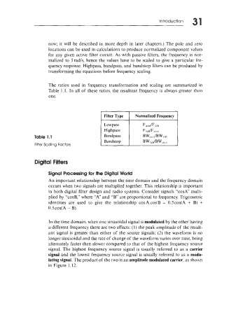
The ratios used in frequency transformation and scaling are summarized in
Table 1.1. In all of these ratios, the resultant frequency is always greater than
one.
Table 1.1
filter Scaling factors
Digital Filters
Signal Processing for the Digital World
An important relationship between the time domain and the frequency domain
occurs when two signals are multiplied together. This relationship is important
in both digital filter design and radio systems. Consider signals “cosA” multi-
plied by “cosB,” where “A” and “B” are proportional to frequency. Trigometric
identities are used to give the relationship cosA.cosB = O.Scos(A + B) +
O.~COS(A B).
-
In the time domain, when one sinusoidal signal is modulated by the other having
a different frequency there are two effects: (1) the peak amplitude of the result-
ant signal is greater than either of the source signals; (2) the waveform is no
longer sinusoidal and the rate of change of the waveform varies over time, being
alternately faster then slower compared to that of the highest frequency source
signal. The highest frequency source signal is usually referred to as a carrier
signal and the lowest frequency source signal is usually referred to as a modu-
lating signal. The product of the two is an amplitude modulated carrier, as shown
in Figure 1.12.