
Page 133 - Analysis and Design of Energy Geostructures
P. 133
Heat and mass transfers in the context of energy geostructures 105
3.9 Principles of mass transfer
Mass transfer is the physical phenomenon for which a net movement of generic parti-
cles is observed from one location to another. One mode of mass transfer is considered
in the following: convection. Additional mass transfer phenomena caused, for example
by diffusive processes exist. However, from an engineering perspective, diffusive mass
transfer processes are considered negligible for the analysis and design of energy
geostructures.
Mass is transferred by convection between any two regions of a continuous system
that are characterised by different hydraulic heads. Hydraulic heads are the potential
variable governing convection mass transfer. The gradient of these variables governs
mass transfer in the same way a temperature gradient characterises heat transfer. The
global hydraulic potential that describes mass transfer is the total head, H. This poten-
tial is made of three contributions that characterise fluids at each point: (1) the eleva-
tion head, h z , due to the weight of the fluid; (2) the pressure head, h p , due to the
static pressure; and (3) the velocity head, h v , due to the bulk motion of the fluid. The
expression of the total head reads
2
H 5 h z 1 h p 1 h v 5 z 1 p f 1 v f ð3:32Þ
γ
f 2g
where z is the elevation of a considered fluid particle above a reference plane, p f is the
fluid pressure, γ is the unit weight of the fluid, v f is the velocity of the fluid at a point
f
on a streamline and g is the gravitational acceleration.
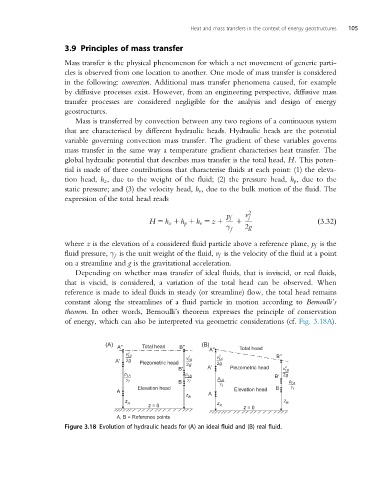
Depending on whether mass transfer of ideal fluids, that is inviscid, or real fluids,
that is viscid, is considered, a variation of the total head can be observed. When
reference is made to ideal fluids in steady (or streamline) flow, the total head remains
constant along the streamlines of a fluid particle in motion according to Bernoulli’s
theorem. In other words, Bernoulli’s theorem expresses the principle of conservation
of energy, which can also be interpreted via geometric considerations (cf. Fig. 3.18A).
(A) A″ Total head B″ (B) A″ Total head
2
2 B″
2
v f,A
A′ v f,B v f,A
Piezometric head 2g
2g
B′ 2g A′ Piezometric head v f,B 2
B′ 2g
p p
f,A f,B
γ γ p
f B f f,A p
f,A
Elevation head γ f B γ
A Elevation head f
A
z
B
z
z B
z = 0 z A
A
z = 0
A, B = Reference points
Figure 3.18 Evolution of hydraulic heads for (A) an ideal fluid and (B) real fluid.